【C++】暴力光栅渲染器(不使用任何图形学API)
介绍
制作这个软件光栅渲染器旨在于熟悉实时渲染管线流程,不是为了优化算法啥的。所以这里不作任何优化,能出图就算成功。
GitHub:https://github.com/1keven1/Raster-Render
在学习了闫令琪大佬的课程之后制作,课程链接:https://sites.cs.ucsb.edu/~lingqi/teaching/games101.html
使用Eigen库实现矩阵和向量储存以及运算,使用OpenCV库显示图像;
使用y轴向上的右手系(别问为啥,我就想用右手系);像素着色器后相机看向z轴反方向,向上坐标为y轴正方向;像素编号以屏幕左下角开始,记录像素左下角的值。
初步实现——渲染三角形
思路:
- 输入物体信息
- 输入相机信息
- 初始化光栅化器
- 顶点着色器:
- 根据摄像机位置对三角形进行矩阵变换
- 片元着色器:
- 逐三角形计算每个像素内的最终颜色
- 将颜色信息存入framebuffer
- 显示图像
类设计——Triangle
三角形包含三个顶点的坐标和每个顶点的颜色,这里使用齐次坐标:
1 | class Triangle |
头文件——global.h
1 | constexpr double PI = 3.1415926; |
摄像机:
1 | struct Camera |
物体:
1 | struct Object |
类设计——Rasterizer(光栅化器)
变量
1
2
3
4
5
6
7
8
9
10
11private:
int width, height; //视口宽高
//顶点着色器相关矩阵
Matrix4f model, view, projection;
Matrix4f mvp;
Matrix4f viewport;
//Buffer
std::vector<Vector3f> frameBuffer;
std::vector<float> depthBuffer;构造函数
1
2
3
4
5
6
7
8
9
10
11Rasterizer::Rasterizer(int w, int h) :width(w), height(h)
{
//分配Buffer空间
frameBuffer.resize(w * h);
depthBuffer.resize(w * h);
viewport << width / 2, 0, 0, width / 2,
0, height / 2, 0, height / 2,
0, 0, 1, 0,
0, 0, 0, 1;
}Clear函数:清空Buffer中的数据
1
2
3
4
5void Rasterizer::Clear()
{
std::fill(frameBuffer.begin(), frameBuffer.end(), Vector3f(0, 0, 0));
std::fill(depthBuffer.begin(), depthBuffer.end(), std::numeric_limits<float>::infinity());
}Vertex Shader
在顶点着色器,我们需要首先对模型施加变换,也就是在Object结构体中定义的平移旋转缩放,写出模型变换(Model Transformation)矩阵;然后把相机移动到原点,并旋转到看向z轴负方向,向上坐标为y轴正方向,写出视图变换(View Transformation)矩阵;最后,将视锥“挤”成[-1,1]^3的正则化体积,并且将正方体中心移动到原点,写出投影变换(Projection Transformation)矩阵。
模型矩阵
模型矩阵的原理比较简单。将旋转分解成xyz轴三个轴的旋转,分别写出对应矩阵,相乘后便得到了旋转矩阵;需要注意旋转和缩放默认都是以原点为中心,而平移操作会改变旋转中心位置,所以平移矩阵一定要最后左乘,也就是乘在最左边。
C++代码实现:
1
2
3
4
5
6
7
8
9
10
11
12
13
14
15
16
17
18
19
20
21
22
23
24
25
26
27
28
29
30
31
32
33
34void Rasterizer::setModelMatrix(const Object& o)
{
Matrix4f rX, rY, rZ; //XYZ轴的旋转矩阵
float radX, radY, radZ; //xyz轴的旋转弧度
Matrix4f scale; //缩放矩阵
Matrix4f move; //位移矩阵
radX = toRadian(o.rotation.x());
radY = toRadian(o.rotation.y());
radZ = toRadian(o.rotation.z());
rX << 1, 0, 0, 0,
0, cos(radX), -sin(radX), 0,
0, sin(radX), cos(radX), 0,
0, 0, 0, 1;
rY << cos(radY), 0, sin(radY), 0,
0, 1, 0, 0,
-sin(radY), 0, cos(radY), 0,
0, 0, 0, 1;
rZ << cos(radZ), -sin(radZ), 0, 0,
sin(radZ), cos(radZ), 0, 0,
0, 0, 1, 0,
0, 0, 0, 1;
scale << o.scale.x(), 0, 0, 0,
0, o.scale.y(), 0, 0,
0, 0, o.scale.z(), 0,
0, 0, 0, 1;
move << 1, 0, 0, o.position.x(),
0, 1, 0, o.position.y(),
0, 0, 1, o.position.z(),
0, 0, 0, 1;
//矩阵左乘计算出模型矩阵
model = move * scale * rZ * rY * rX;
}视图矩阵
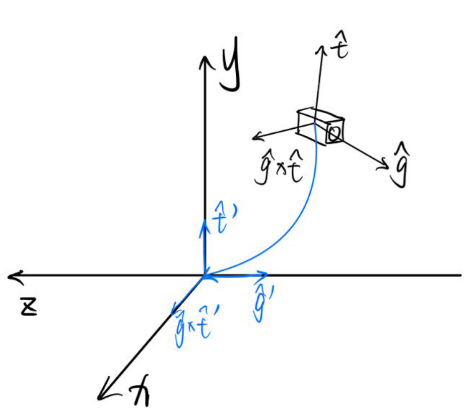
视图矩阵要将摄像机变换为在原点、看向-z方向,头顶是y方向的标准形态。

第一步是把摄像机移动到原点,这步非常简单,构建平移矩阵即可;
第二步是旋转摄像机,这里需要用到旋转矩阵的一个性质——旋转矩阵为正交矩阵。这就表示任何旋转矩阵的逆矩阵就是他的转置。因此,既然从摄像机现在的状态旋转到标准状态的矩阵不好写,那就先写出从标准状态转换成当前状态的矩阵,再求个逆就好了。摄像机现在的状态即为z轴转到-g方向,y轴转到t方向,x轴转到g×t方向,因此:
C++程序实现:
1
2
3
4
5
6
7
8
9
10
11
12
13
14
15
16
17
18
19void Rasterizer::setViewMatrix(const Camera& c)
{
//将摄像机移动到原点,然后使用旋转矩阵的正交性让摄像机摆正
Matrix4f t; //移动矩阵
Vector3f cX; //摄像机的x轴
Matrix4f r; //旋转矩阵的旋转矩阵
t << 1, 0, 0, -c.position.x(),
0, 1, 0, -c.position.y(),
0, 0, 1, -c.position.z(),
0, 0, 0, 1;
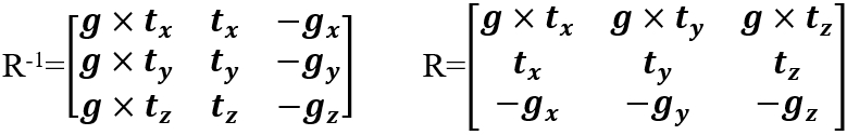
cX = c.g.cross(c.t);
r << cX.x(), cX.y(), cX.z(), 0,
c.t.x(), c.t.y(), c.t.z(), 0,
-c.g.x(), -c.g.y(), -c.g.z(), 0,
0, 0, 0, 1;
//矩阵左乘计算出视图矩阵
view = r * t;
}透视投影矩阵
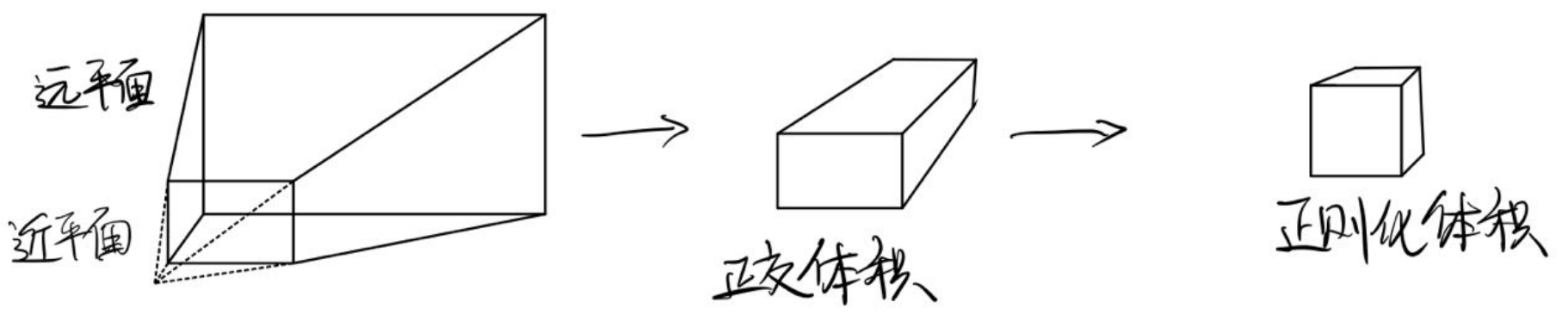
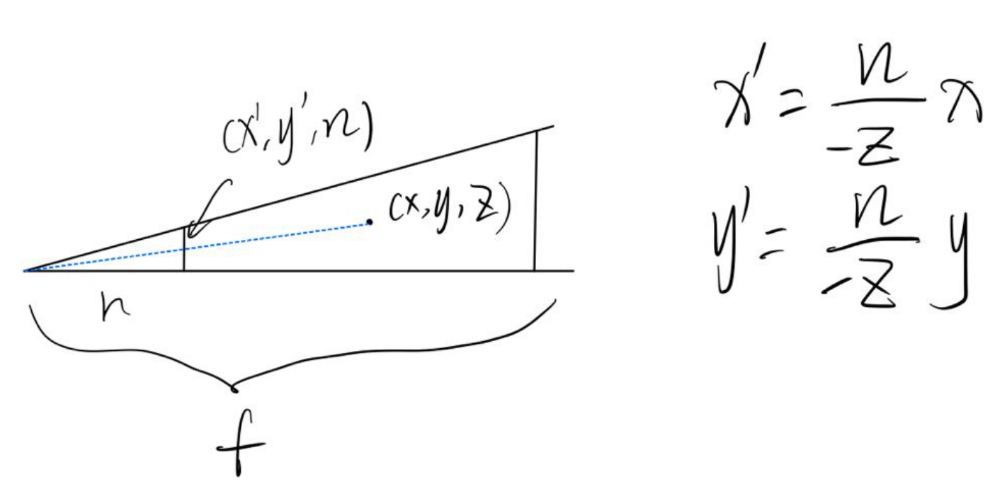
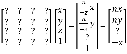
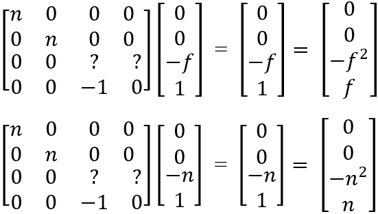
透视矩阵是最复杂的一个,需要进行代数计算。我们需要首先把梯台形状的透视视锥挤压成长方体状正交体积,然后将此体积平移并挤压成[-1,1]^3的正则化体积。
在第一个过程中,近平面上所有点和远平面中心点不变,因此有个未知矩阵M:
又因为在齐次坐标中,四个值同时乘以一个非零值,其表示的意义不变,所以都乘以-z:
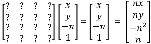
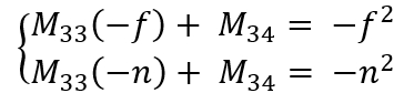
如果点在近平面上,也就是z值为n,那么前后将不变(注意这里n是正数,z是负数):
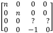
由这个式子可以确定矩阵M的绝大多数数值:
而剩下两个值需要用到远平面和近平面中心不变:
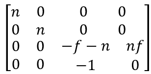
易解得矩阵M为:
第二个过程就比较简单了,只是将正交体积中心挪到原点然后缩放至边长为2即可。
1
2
3
4
5
6
7
8
9
10
11
12
13
14
15
16
17
18
19
20
21
22
23
24
25
26
27void Rasterizer::setProjectionMatrix(const Camera& c)
{
//透视投影矩阵
Matrix4f p2o; //将梯台状透视视锥挤成长方体正交投影
Matrix4f orthoTrans, orthoScale, ortho; //正交投影矩阵的平移和缩放分解
float t, r; //近平面的上边界和右边界
float radFov; //视野的弧度制
radFov = toRadian(c.fov);
t = tan(radFov / 2) * c.nNear;
r = c.aspectRatio * t;
p2o << c.nNear, 0, 0, 0,
0, c.nNear, 0, 0,
0, 0, c.nFar + c.nNear, c.nNear* c.nFar,
0, 0, -1, 0;
orthoTrans << 1, 0, 0, 0,
0, 1, 0, 0,
0, 0, 1, (c.nNear + c.nFar) / 2,
0, 0, 0, 1;
orthoScale << 1 / r, 0, 0, 0,
0, 1 / t, 0, 0,
0, 0, 2 / (c.nFar - c.nNear), 0,
0, 0, 0, 1;
ortho = orthoScale * orthoTrans;
//矩阵左乘计算出透视投影矩阵
projection = ortho * p2o;顶点着色器主程序:
1
2
3
4
5
6
7
8
9
10
11
12
13
14
15
16
17
18
19
20
21
22
23
24
25
26
27
28
29
30void Rasterizer::VertexShader(std::vector<Object>& objectList, Camera c)
{
//对于每个物体
for (Object& object : objectList)
{
//计算MVP矩阵
SetModelMatrix(object);
SetViewMatrix(c);
SetProjectionMatrix(c);
mvp = projection * view * model;
//std::cout << mvp;
//对于物体中的每个三角形
for (Triangle& t : object.triangles)
{
//对于三角形的每个顶点
for (auto& vec : t.v)
{
//变换
vec = mvp * vec;
vec = viewport * vec;
//齐次坐标归一化
vec.x() /= vec.w();
vec.y() /= vec.w();
vec.z() /= vec.w();
vec.w() /= vec.w();
}
}
}
return;
}
Fragment Shader
在片段着色器中,我们绘制每个三角形的Bounding Box,遍历其中的每一个像素。如果该像素中心在三角形内的话,对深度进行差值检测深度。若深度小于Depth Buffer中的值,则根据三角形重心坐标进行差值,并更改Frame Buffer中储存的数据。
检测点是否在三角形内:使用向量叉乘判断正负号的性质:
1
2
3
4
5
6
7
8
9
10
11
12
13
14
15
16
17
18
19
20
21
22
23
24
25
26
27
28
29
30
31bool Rasterizer::InsideTriangle(const float x, const float y, const Triangle& t)
{
Vector3f v[3] =
{
Vector3f(t.v[0].x(),t.v[0].y(),1.f),
Vector3f(t.v[1].x(),t.v[1].y(),1.f),
Vector3f(t.v[2].x(),t.v[2].y(),1.f)
};
Vector3f p(x, y, 1);
//三条边的向量
Vector3f side1, side2, side3;
side1 = v[1] - v[0];
side2 = v[2] - v[1];
side3 = v[0] - v[2];
//顶点到点的向量
Vector3f p1, p2, p3;
p1 = p - v[0];
p2 = p - v[1];
p3 = p - v[2];
//叉乘
Vector3f cross1, cross2, cross3;
cross1 = p1.cross(side1);
cross2 = p2.cross(side2);
cross3 = p3.cross(side3);
//判断是否同号
if ((cross1.z() > 0 && cross2.z() > 0 && cross3.z() > 0) || (cross1.z() < 0 && cross2.z() < 0 && cross3.z() < 0))
{
return true;
}
else return false;
}计算2D重心坐标:
1
2
3
4
5
6
7std::tuple<float, float, float> Rasterizer::Barycentric2D(float x, float y, const Vector4f* v)
{
float c1 = (x * (v[1].y() - v[2].y()) + (v[2].x() - v[1].x()) * y + v[1].x() * v[2].y() - v[2].x() * v[1].y()) / (v[0].x() * (v[1].y() - v[2].y()) + (v[2].x() - v[1].x()) * v[0].y() + v[1].x() * v[2].y() - v[2].x() * v[1].y());
float c2 = (x * (v[2].y() - v[0].y()) + (v[0].x() - v[2].x()) * y + v[2].x() * v[0].y() - v[0].x() * v[2].y()) / (v[1].x() * (v[2].y() - v[0].y()) + (v[0].x() - v[2].x()) * v[1].y() + v[2].x() * v[0].y() - v[0].x() * v[2].y());
float c3 = (x * (v[0].y() - v[1].y()) + (v[1].x() - v[0].x()) * y + v[0].x() * v[1].y() - v[1].x() * v[0].y()) / (v[2].x() * (v[0].y() - v[1].y()) + (v[1].x() - v[0].x()) * v[2].y() + v[0].x() * v[1].y() - v[1].x() * v[0].y());
return { c1,c2,c3 };
}这里其实直接使用2D重心坐标有问题,因为三角形经过视口投影到屏幕上,屏幕上的三角形的重心坐标与实际重心坐标并不相符,这里应该将三角形乘以视口变换矩阵的逆矩阵变换回空间中在进行计算
根据重心坐标所得值进行线性插值函数:目前有两个重载
1
2
3
4
5
6
7
8
9Vector3f Rasterizer::Interpolate(float alpha, float beta, float gamma, const Vector3f& vert1, const Vector3f& vert2, const Vector3f& vert3)
{
return (alpha * vert1 + beta * vert2 + gamma * vert3);
}
float Rasterizer::Interpolate(float alpha, float beta, float gamma, const float& vert1, const float& vert2, const float& vert3)
{
return (alpha * vert1 + beta * vert2 + gamma * vert3);
}设置像素颜色:因为OpenCV从左上角开始绘制像素,所以屏幕高度减去y值再减一为前面有多少行。
1
2
3
4
5void Rasterizer::SetPixelColor(const Vector2i point, const Vector3f color)
{
int ind = (height - point.y() - 1) * width + point.x();
frameBuffer[ind] = color;
}
片元着色器主程序:
1
2
3
4
5
6
7
8
9
10
11
12
13
14
15
16
17
18
19
20
21
22
23
24
25
26
27
28
29
30
31
32
33
34
35
36
37
38
39
40
41
42
43
44
45
46
47
48
49
50
51
52
53
54
55
56
57
58
59void Rasterizer::FragmentShader(std::vector<Object>& objectList)
{
for (Object& object : objectList)
{
for (Triangle& t : object.triangles)
{
//绘制bounding box
float minXf, maxXf, minYf, maxYf;
minXf = width;
maxXf = 0;
minYf = height;
maxYf = 0;
for (const auto& ver : t.v)
{
if (ver.x() < minXf) minXf = ver.x();
if (ver.x() > maxXf) maxXf = ver.x();
if (ver.y() < minYf) minYf = ver.y();
if (ver.y() > maxYf) maxYf = ver.y();
}
if (minXf < 0) minXf = 0;
if (maxXf > width) maxXf = width;
if (minYf < 0) minYf = 0;
if (maxYf > height) maxYf = height;
//取整
int minX, maxX, minY, maxY;
minX = floor(minXf);
maxX = ceil(maxXf);
minY = floor(minYf);
maxY = ceil(maxYf);
//对bounding box中的每一个像素
for (int y = minY; y < maxY; ++y)
{
for (int x = minX; x < maxX; ++x)
{
//判断像素中心是否在三角形内
if (InsideTriangle((float)x + 0.5, (float)y + 0.5, t))
{
//在的话计算2D重心坐标
float alpha2D, beta2D, gamma2D;
std::tie(alpha2D, beta2D, gamma2D) = Barycentric2D((float)x + 0.5f, (float)y + 0.5f, t.v);
float w = alpha2D + beta2D + gamma2D;
float interpolateZ2D = Interpolate(alpha2D, beta2D, gamma2D, t.v[0].z(), t.v[1].z(), t.v[2].z());
interpolateZ2D /= w;
//判断深度值
if (depthBuffer[GetPixelIndex(x, y)] > interpolateZ)
{
//深度更近的话插值出颜色,然后更新深度信息
Vector3f interpolateColor = Interpolate(alpha, beta, gamma, t.color[0], t.color[1], t.color[2]);
Vector3f pixelColor = interpolateColor;
SetPixelColor(Vector2i(x, y), pixelColor);
depthBuffer[GetPixelIndex(x, y)] = interpolateZ;
}
}
}
}
}
}
}
类设计——Shader
这里为了以后方便,新建一个Shader类,负责根据输入的信息计算返回的颜色值。
1 | if (depthBuffer[GetPixelIndex(x, y)] > interpolateZ) |
这里的shader很简单,输入插值后的颜色,直接将颜色返回。
1 | Vector3f BaseVertexColor() |
主程序
1 | constexpr int width = 700; |
首先设置两个物体,是两个三角形:
1
2
3
4
5
6
7
8
9
10
11
12
13
14
15
16
17
18
19
20
21
22
23
24
25void SetObjects()
{
//o1
Object o1;
Triangle t1;
t1.setVertex(Vector3f(0, 2, -2), Vector3f(-2, 0, -2), Vector3f(1, 0, -2));
t1.setColor(Vector3f(225, 0, 0), Vector3f(0, 225, 0), Vector3f(0, 0, 225));
o1.triangles.push_back(t1);
o1.position = Vector3f(0, 0, 0);
o1.rotation = Vector3f(0, 0, 0);
o1.scale = Vector3f(2, 2, 1);
objectList.push_back(o1);
//o2
Object o2;
Triangle t2;
t2.setVertex(Vector3f(2, 1, 0), Vector3f(-2, 4, -5), Vector3f(-1, -3, -5));
t2.setColor(Vector3f(100, 100, 100), Vector3f(100, 100, 100), Vector3f(100, 100, 100));
o2.triangles.push_back(t2);
o2.position = Vector3f(0, 0, 0);
o2.rotation = Vector3f(0, 0, 0);
o2.scale = Vector3f(1, 1, 1);
objectList.push_back(o2);
}然后设置相机:
1
2
3
4
5
6
7
8
9
10void SetCamera()
{
camera.position = Vector3f(0, 0, 10);
camera.g = Vector3f(0, 0, -1).normalized();
camera.t = Vector3f(0, 1, 0).normalized();
camera.fov = 45.f;
camera.nNear = 0.1f;
camera.nFar = 50.f;
camera.aspectRatio = width / height;
}主程序:
1
2
3
4
5
6
7
8
9
10
11
12
13
14
15
16
17
18
19
20
21
22
23
24
25
26
27int main()
{
SetObjects(); //输入物体
SetCamera(); //设置相机
//初始化光栅化器
Rasterizer r(width, height);
do
{
r.Clear();
std::vector<Object> list = objectList; //复制一份出来共光栅化器处理
//光栅化
r.VertexShader(list, camera);
r.FragmentShader(list);
//绘制
cv::Mat image(height, width, CV_32FC3, r.GetFrameBuffer().data());
image.convertTo(image, CV_8UC3, 1.0f);
cv::cvtColor(image, image, cv::COLOR_RGB2BGR);
cv::imshow("image", image);
cv::waitKey(0);
std::cout << frameCount++ << std::endl;
} while (0);
return 0;
}
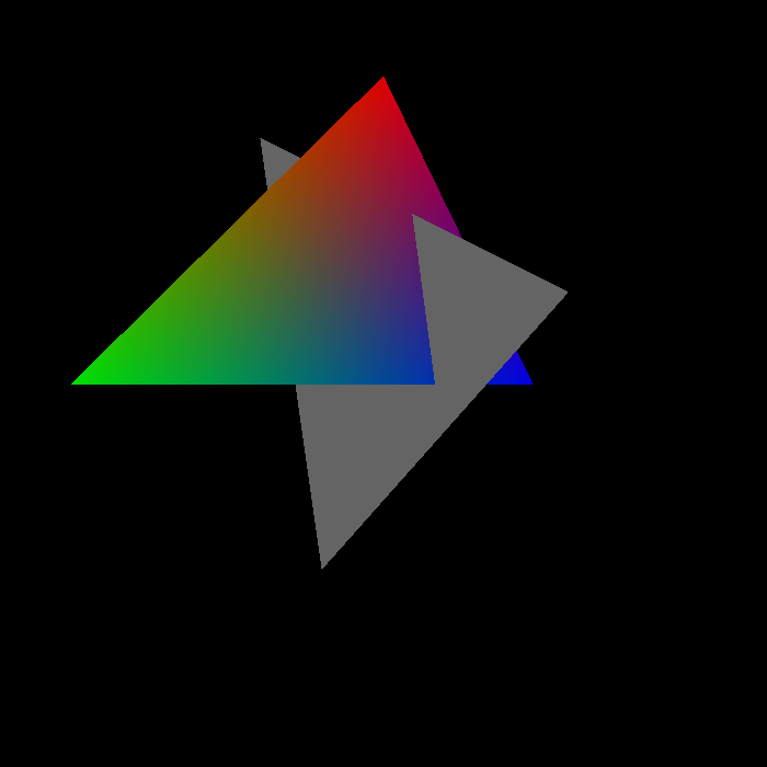
至此,就可以正确的渲染出来两个三角形,正确地检测深度,正确地插值了:
现在的效果已经不错了,然后我们把前面说的计算三维重心坐标的问题解决一下:
具体原理解释如下图(虎书2.7节):
1 | std::tuple<float, float, float> Rasterizer::Barycentric3D(const Vector4f& point, const Vector4f* v) |
更改程序:
1 | if (InsideTriangle((float)x + 0.5, (float)y + 0.5, t)) |
整点r骚的:
添加功能——暴力MSAA抗锯齿
MSAA,全称Multi Sample Anti-Aliasing,也就是多重采样抗锯齿。顾名思义,就是一个像素采样很多次,再求平均为像素着色,这样如果这个像素只有一部分在三角形内就会有不同的颜色,进而产生抗锯齿的效果。当然采样时间的增加也是无法避免的。
现在,为了让在尽量少的采样点数量下获得尽可能高的抗锯齿效果,每个像素采样点的位置都很有讲究。可惜,我不管这些,我这次就直接写一个一个像素采样四次的暴力算法,熟悉一下原理就行了。
我直接将像素分成四块,在四块的中心分别采样,看看在不在三角形内,看看颜色是啥,然后把四块的信息求个平均就是这个像素的颜色。
既然暴力,那就必然会大幅度降低渲染速度,咱这又是个小破r单线程渲染器,所以在global.h中设置个开关:
1 | constexpr bool MSAA4X = true; |
初始化的时候分配更大的Depth Buffer:
1 | if (!MSAA4X) depthBuffer.resize(w * h); |
1 | else //MSAA4X |
1 | //求平均并设置颜色 |
效果还算不错(可惜渲染时间太长了,后面默认关掉):

添加功能——导入.obj文件
导入OBJ文件肯定不是那么简单的,这里我们就用一个开源的头文件OBJ_Loader.h,是由Robert Smith创作,Github链接:https://github.com/Bly7/OBJ-Loader
在头文件引用一下就好了。
导入三角形
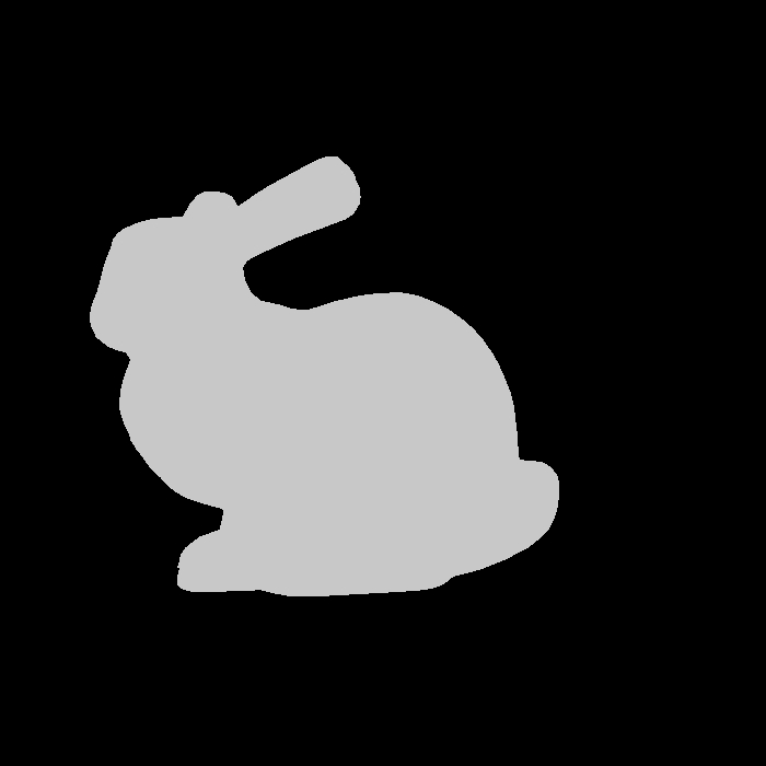
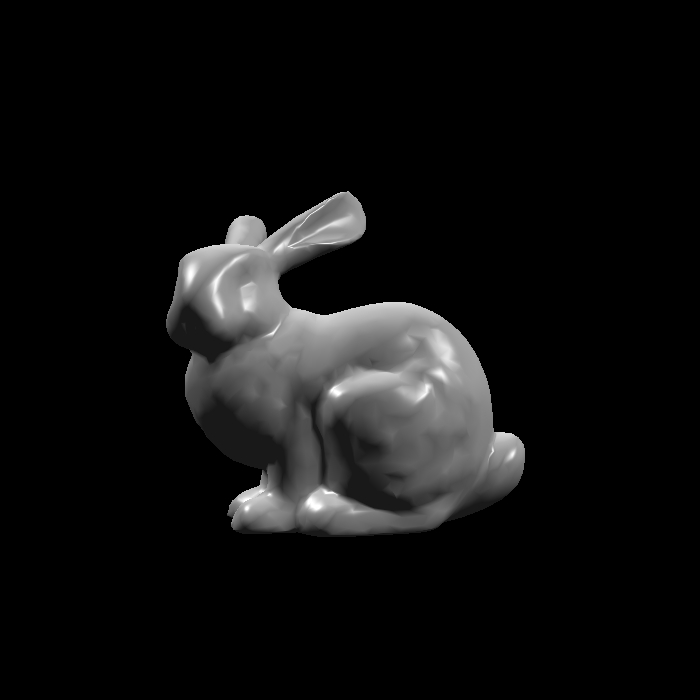
我们一步一步来,首先完成导入三角形的测试。在文件里放个兔子Bunny的模型,输入相对路径即可,这里为了能看到模型随意给了个顶点色。
1 | void SetModel() |
稍微调整一下模型缩放和位置,就可以得到结果了:
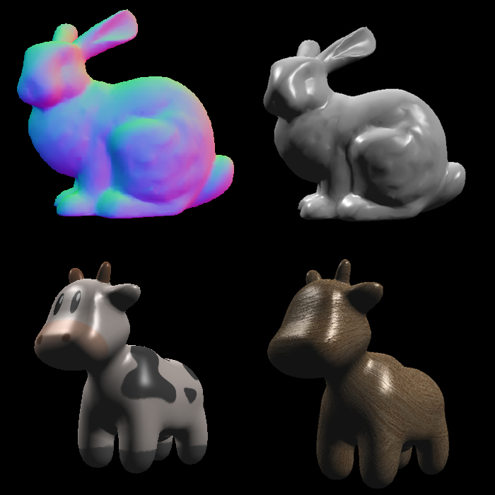
导入法线
这么渲染完全看不出来立体感,这一步我们加上法线。
首先在三角形类中添加法线数组和设置法线的函数:
1 | //设置法线 |
然后在载入模型的地方导入法线:
1 | t->SetNormal(j, Vector3f(mesh.Vertices[i + j].Normal.X, mesh.Vertices[i + j].Normal.Y, mesh.Vertices[i + j].Normal.Z)); |
片元着色器中对法线进行线性插值:
1 | auto interpolateNormal = Interpolate(alpha3D, beta3D, gamma3D, t.normal[0], t.normal[1], t.normal[2]).normalized(); |
编写新的shader函数用于显示法线,因为法线的三个向量值域均为[-1, 1],而颜色值的值域为[0, 1],所以将法线值加上1再除以2即可(这也是为啥法线贴图是紫色的):
1 | Vector3f NormalShader() |
在光栅化器中将函数更换为NormalShader()即可渲染出结果:
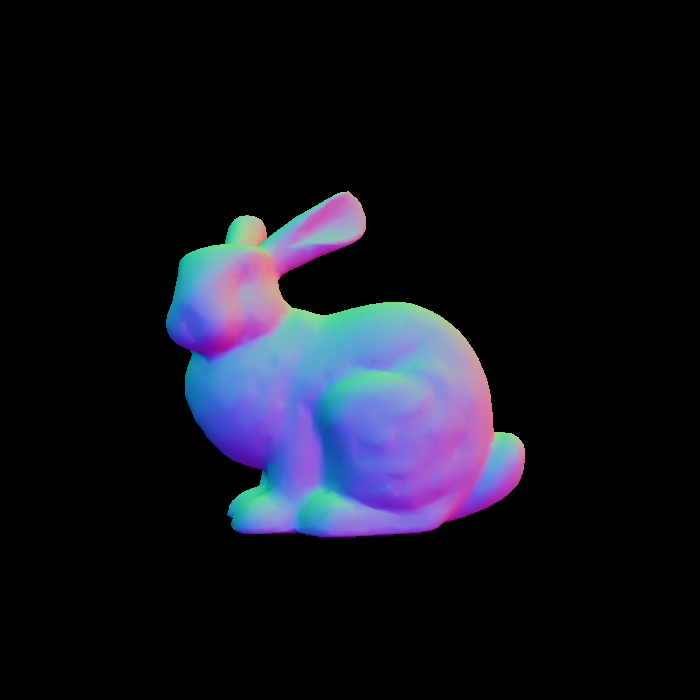
瞬间有立体感了撒。
为了方便后续操作,将使用枚举值控制使用的Shader函数:
1 | Vector3f Shading() |
添加光照——Blinn-Phong反射模型
Blinn-Phong光照模型并不十分物理正确,只是非常简单且可以获得较为正确的视觉结果
原理
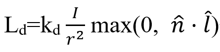
漫反射(Diffuse)
接受的能量与光源方向l与面法线n的夹角θ有关,因为l与n都是单位向量,所以就是l·n有关,因此有公式:
其中kd为漫反射系数,也就是颜色;I/r^2是光源到达此点的能量系数,其中I是光源强度,r是光源到此点的距离。
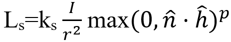
高光(Specular)
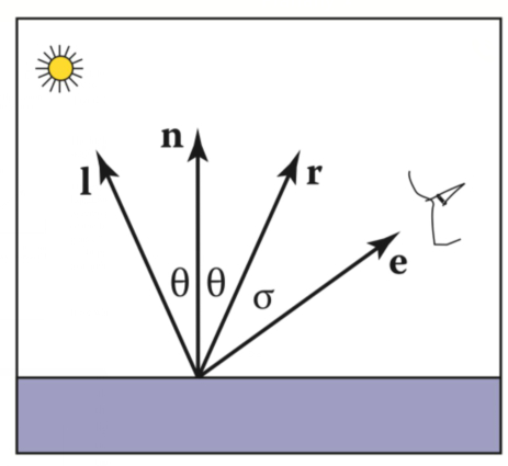
如下图,高光值应该在e接近r的时候出现,使用e·r就可以检测e与r的距离近不近。
但是r不好算,所以咱们换一种方法,就是求e与l的中间的单位向量h,也就是半程向量,检测这个向量与面法线n的夹角即可:
因此有公式:
其中p是控制高光大小的指数值
环境光(Ambient)
这里不做复杂的计算,就默认每盏灯都会贡献一定量的环境光照。
所以这里Shader需要的数据有:光源信息,观察方向,法线,表面属性(颜色,高光度等),还有环境光、漫反射和高光的吸收系数。
在global.h文件中添加光源结构体:
1 | struct Light |
在顶点着色器中,灯光也要应用视角变换:
1 | //对于每个光源 |
Blinn-Phong Shader:
1 | Vector3f BlinnPhongShader() |
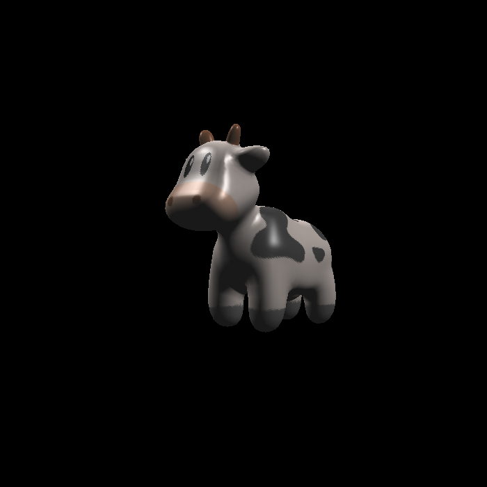
然后就出图嘞,效果异常的好呢!
添加贴图——纹理映射(Texture Mapping)
添加漫反射贴图
既然是贴图,那三角形每个顶点必然得有一个纹理坐标,也就是UV坐标:
1 | void SetTexCoord(const int& i, const Vector2f& tC) |
然后依旧是导入纹理坐标:
1 | t->SetTexCoord(j, Vector2f(mesh.Vertices[i + j].TextureCoordinate.X, mesh.Vertices[i + j].TextureCoordinate.Y)); |
对纹理坐标进行插值,传入shader:
1 | auto interpolateTexCoord = Interpolate(alpha3D, beta3D, gamma3D, t.texCoord[0], t.texCoord[1], t.texCoord[2]); |
然后新建一个贴图类,负责加载贴图以及根据纹理坐标返回颜色值:
1 | class Texture |
将贴图传入shader,在渲染时判断贴图是否可用,可用用贴图,不可用用顶点色。既然要判断是否可用,那就会用到类模板std::optional:
1 | std::optional<Texture> texture; |
并添加SetTexture函数。
在主程序中加载贴图:
1 | void SetTexture(Rasterizer& r) |
在shader中添加贴图指针和渲染函数,基本都与Blinn-Phong相同,只是漫反射系数直接使用贴图颜色:
1 | Vector3f TextureShader() |
在光栅化器中为shader载入贴图
1 | shader.SetTexture(texture ? &*texture : nullptr); |
这里使用Keenan Crane (keenan@cs.caltech.edu)制作的开源spot模型以及贴图:
贴图的双线性插值(Bilinear Interpolation)
选取最近的4个贴图像素,进行两个方向三次线性插值,已达到贴图抗锯齿效果:
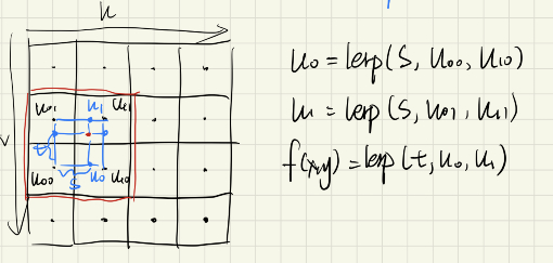
1 | if (BLERP)//双线性插值 |
把贴图压到512*512(之前是1k),测试一下:
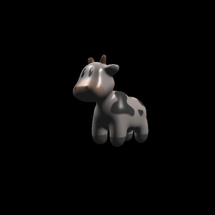
从眼睛部分还是能看出很大区别的。
添加凹凸贴图(Bumping Map)
正常加载一个凹凸贴图。
具体原理较为复杂,这里有:https://blog.csdn.net/yjr3426619/article/details/81022781
1 | Vector3f TextureWithBump() |
我随便找了一个木纹理的法线贴图ps转换成凹凸贴图:

添加法线贴图(Normal Map)
与凹凸贴图类似:
1 | Vector3f TextureWithNormal() |
随便找了一张水滴的法线贴图:

到这里,软件光栅渲染器的基本功能就都完成嘞,既然完事r了,就来几张好玩r的渲渲:
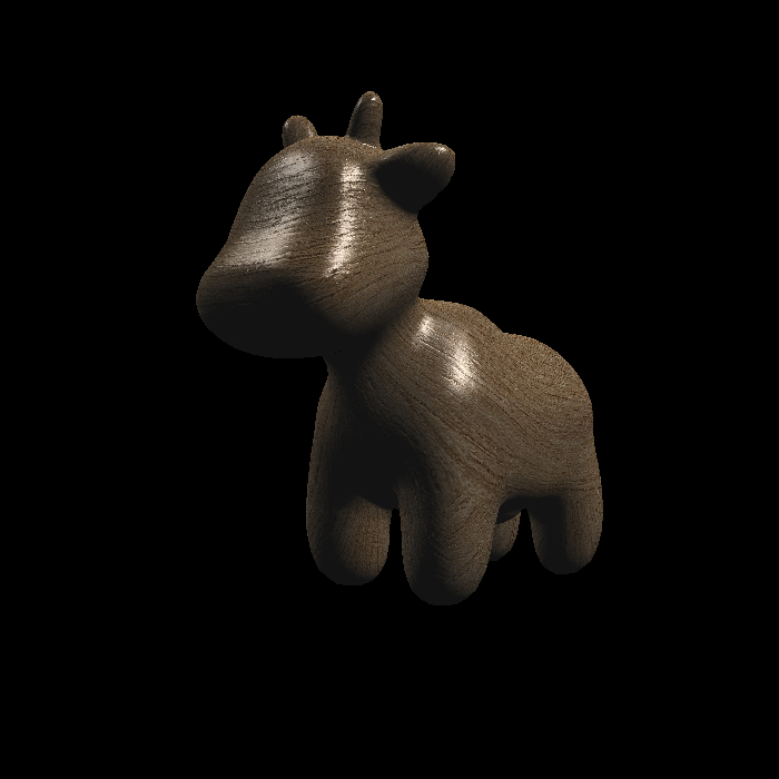
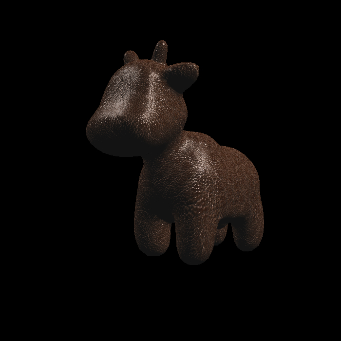
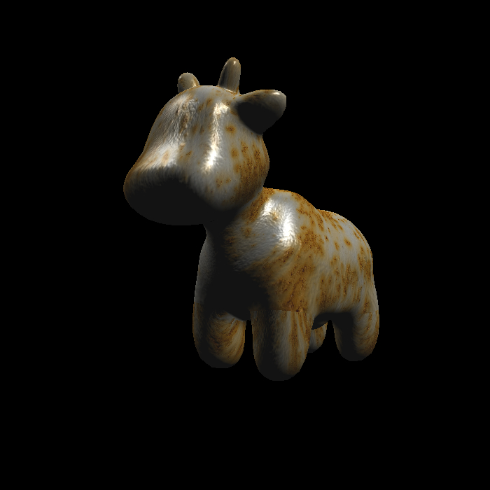
不错,做这些就是为了玩r呢!
其他优化
- 背面剔除:光栅化器中检测法线方向,如果法线方向不向着相机则不渲染。
还存在的一些问题
- 在真实的实时渲染管线中,在顶点着色器中首先将所有顶点进行变换,而后再连成三角形,因为三角形有很多复用的顶点,这样会节省一定性能。这里由于大部分性能消耗都在光栅化阶段,所以就不做这方面的改进了。
- MSAA的算法还存在问题,现在是每个像素维护自己的4个深度值,并着色的时候与玄素原颜色进行平均,这会导致三角形边缘有偏向背景色的描边(所以后期一直妹开),有待解决。
- 在进行渲染前应该对超出摄像机近平面和远平面的三角形进行剪裁,否则会出现错误的结果,这里没有做。
- 剩下的类似视锥剔除等高阶操作也都没有做。
- 214
- 微信
- 支付宝